Garrie AI: Your Cable Guide


Wiring for Minimum Circuit Ampacity
Minimum circuit ampacity (MCA) is the smallest ampacity the supply conductors for an air conditioner, heat pump, or refrigeration unit may have. The manufacturer calculates it and prints it on the nameplate, and the NEC requires the branch-circuit wire to meet or exceed it. Its partner value, maximum overcurrent protection (MOCP), sets the largest breaker or fuse the circuit may use.
Three rules cover wiring for minimum circuit ampacity:
-
Size the wire to the MCA. The 125% motor allowance is already inside that number.
-
Size the breaker or fuse at or below the MOCP.
-
Correct the wire for ambient temperature, conductor count, and terminal rating before you pick a gauge.
This guide explains what MCA and MOCP mean, how manufacturers calculate them under NEC Article 440, and how to select conductor size, breaker rating, and cable type for an HVAC branch circuit. Section numbers follow the 2023 NEC. Check which edition your authority having jurisdiction (AHJ) enforces, since 2026 NEC adoption is now under way.
What Is Minimum Circuit Ampacity (MCA)?
Minimum circuit ampacity is the lowest current-carrying capacity, in amperes, that the branch-circuit conductors feeding a piece of air-conditioning or refrigeration equipment may have. It is a floor for the wire, not a breaker size, and not the current the unit draws while running.
NEC 440.4(B) requires that multimotor and combination-load equipment, which covers almost every condensing unit, heat pump, and packaged rooftop unit, carry a nameplate listing the minimum supply-circuit conductor ampacity and the maximum rating of the branch-circuit short-circuit and ground-fault protective device. NEC 440.35 then requires the branch-circuit conductors to be no smaller than that marked ampacity. NEC 110.3(B) closes the loop: listed equipment must be installed according to its listing and labelling, so the nameplate value governs.
What Does MCA Stand For in Electrical Terms?
In electrical work, MCA stands for Minimum Circuit Ampacity. The abbreviation appears on nameplates in several forms:
-
MCA
-
M.C.A.
-
MIN. CIRCUIT AMPACITY
-
MIN. SUPPLY CIRCUIT AMPACITY
-
MIN. CKT. AMPS
MCA Amps: What the Number Tells You
MCA is expressed in amps, often with one decimal place, such as 22.1 A or 47.5 A. The figure is not rounded to a wire size or breaker size. The installer selects the smallest conductor whose corrected ampacity is equal to or exceeds the required value.
The number already includes the NEC 125% allowance for the largest motor. The extra 25% keeps a conductor that carries a compressor for hours at a time from running at the edge of its rating. It is the same margin as the familiar 80% rule for continuous loads in NEC 210.19(A)(1) and 210.20(A), seen from the other side: 1 ÷ 1.25 = 0.8, so a conductor sized at 125% of the compressor current carries that current at 80% of its ampacity. Because the allowance is built in, the installer never multiplies the MCA by 1.25 again.
How Manufacturers Calculate MCA
Manufacturers calculate MCA from the rated-load current (RLA) of each compressor and the full-load current (FLA) of each fan or blower motor. The installer does not need to repeat the math, but knowing it helps when a label is missing, faded, or questioned by an inspector.
For a single motor-compressor, NEC 440.32 sets the conductor ampacity at 125% of the rated-load current or the branch-circuit selection current, whichever is greater. For equipment with several motors, NEC 440.33 adds 25% of the largest motor to the sum of all motor currents. Combination loads, such as a unit with electric heat strips, follow NEC 440.34 and add the other loads at 100%.
Here is the formula:
MCA = 1.25 × largest compressor RLA + other compressor RLAs + fan FLAs + other loads
Only the largest motor receives the 125% factor. Everything else, including fan motors, crankcase heaters, and controls, counts at 100%.
MCA Example
A 208/230 V single-phase condensing unit lists a compressor RLA of 16.7 A and an outdoor fan FLA of 1.2 A. The calculation is (1.25 × 16.7) + 1.2 = 20.875 + 1.2 = 22.075 A, which the nameplate shows as an MCA of 22.1 A. The branch-circuit conductors for this unit must have an ampacity of at least 22.1 A after all corrections.
What Is Maximum Overcurrent Protection (MOCP)?
Maximum overcurrent protection is the largest breaker or fuse rating permitted on the branch circuit supplying the equipment. Where MCA sets the floor for the wire, MOCP sets the ceiling for the protective device.
The branch-circuit breaker on an HVAC circuit protects against only short circuits and ground faults. The compressor carries its own overload protection under Part VI of Article 440, so the breaker can run well above the MCA without leaving the motor unprotected. That margin lets the unit ride through the locked-rotor inrush at startup without nuisance trips. Article 440 supplements the general motor rules in Article 430 for hermetic compressors. It sizes from the nameplate RLA or branch-circuit selection current instead of the Article 430 motor tables [440.6(A)], and it sets its own breaker limits in 440.22 instead of Table 430.52.
MOCP Meaning in Electrical Work
MOCP electrical meaning: the maximum rating of the branch-circuit short-circuit and ground-fault protective device, as marked on the equipment under NEC 440.4(B). Nameplates print it in several ways:
-
MOCP (maximum overcurrent protection)
-
MOP (maximum overcurrent protection)
-
MAX. FUSE
-
MAX. FUSE OR HACR BREAKER
-
MAX. CKT. BKR.
How MOCP Is Calculated
NEC 440.22(A) limits the protective device for an individual motor-compressor to 175% of its rated-load current or branch-circuit selection current. If that rating cannot carry the starting current, the limit rises to 225%. For multimotor equipment, the manufacturer typically calculates:
MOCP = 2.25 × largest compressor RLA + all other loads
The result is rounded down to the nearest standard size listed in NEC 240.6(A). For the example unit, (2.25 × 16.7) + 1.2 = 38.775 A, which rounds down to a 35 A maximum.
HACR Breakers and Fuse-Only Labels
Most residential and light commercial units read "Max. Fuse or HACR Breaker." HACR stands for heating, air-conditioning, and refrigeration, and most modern thermal-magnetic breakers carry the HACR marking. When the label lists only a maximum fuse size, the listing calls for fuses. NEC 110.3(B) requires the installation to follow that marking.
MCA vs FLA: What Is the Difference?
MCA is a circuit-level sizing value. FLA is the running current of one motor. The two sit on the same nameplate, but only MCA sizes the wire.
-
MCA (minimum circuit ampacity): the floor for conductor ampacity for the whole unit, with the 125% allowance already applied. It sizes the wire.
-
MOCP (maximum overcurrent protection): the ceiling for the breaker or fuse. It sizes the protective device.
-
RLA (rated-load amps): the compressor's rated-load current under NEC 440.6(A). It feeds the MCA and MOCP math.
-
FLA (full-load amps): the running current of a fan or blower motor. It is added to the MCA at 100%.
-
LRA (locked-rotor amps): the compressor's inrush at startup, often several times the RLA. It explains why MOCP runs higher than MCA, but it does not size the wire.
Confusing FLA vs MCA, or MCA vs MOCP, leads to three common mistakes. The first is sizing the wire from the fan FLA or the compressor RLA alone, which undersizes the conductor. The second is multiplying the MCA by 1.25 again, which oversizes the conductor and adds cost with no code benefit. The third is sizing the breaker to the MCA, which leaves no room for locked-rotor inrush and trips the breaker when the compressor starts.
How to Wire for Minimum Circuit Ampacity
The same nine checks apply to wiring for minimum circuit ampacity on every job, from a residential condenser to a commercial rooftop unit. The chart below does the core work: find the nameplate MCA in the left column, then read across to the wire size.

Sizes follow the 60°C column of NEC Table 310.16, the default for circuits of 100 A or less under NEC 110.14(C), with up to three current-carrying conductors at 30°C (86°F) ambient. When every termination is marked 75°C, the 75°C column may allow one size smaller. Above 100 A, the 75°C column applies. Correct for hot ambient, rooftop runs, and crowded raceways before you read the chart.
How to read it: the example unit has an MCA of 22.1 A. That value falls in the 20.1–30 A row, so the circuit takes 10 AWG copper or 8 AWG aluminum.
Step by Step: Wiring the Example Unit
The example unit lists MCA 22.1 A, MOCP 35 A, 208/230 V single-phase, with a 100 ft one-way run.
-
Read the nameplate [440.4(B), 110.3(B)]. Record MCA 22.1 A, MOCP 35 A, 208/230 V, 1-phase. The nameplate governs over any rule of thumb.
-
Choose the temperature column [110.14(C)(1)(a)]. The unit terminals are unmarked, so the 60°C column applies.
-
Apply corrections [310.15(B), 310.15(C)(1)]. At 30°C ambient with two current-carrying conductors, no correction applies. Hot attics, rooftops, and crowded raceways change that. Table 310.15(C)(1) multiplies ampacity by 0.80 for 4–6 current-carrying conductors, 0.70 for 7–9, and 0.50 for 10–20. Table 310.15(B)(1) applies 0.88 to a 75°C conductor at 36–40°C (97–104°F), so 12 AWG copper drops from 25 A to 22 A.
-
Select the conductor [440.35, Table 310.16]. The chart points to 10 AWG copper at 30 A.
-
Select the breaker or fuse [440.22, 240.4(G), 240.6(A)]. Use a 30 A or 35 A 2-pole HACR breaker. 35 A on 10 AWG is allowed by 240.4(G).
-
Size the ground wire [250.122]. Size it from the breaker rating, not the MCA: 10 AWG copper for a 35 A breaker.
-
Check voltage drop [210.19, informational note]. 2 × 100 ft × 22.1 A × 1.24 Ω/kft = 5.5 V, or 2.3% at 240 V, which stays under 3%.
-
Install the disconnect [440.14, 440.12]. Place it within sight of the unit. Rate it at 115% or more of the compressor RLA plus the other loads [440.12(B)]: 115% × (16.7 A + 1.2 A) = 20.6 A, so a 30 A disconnect works. A disconnect switch also needs a horsepower rating at least equal to the unit's equivalent horsepower, found from the RLA and LRA [440.12(A)(2)].
-
Choose the cable type [Chapter 3]. Run 10 AWG THWN-2 in PVC outdoors with a liquidtight whip at the unit.
The finished circuit for this unit is 10 AWG copper on a 35 A HACR breaker with a 10 AWG ground. Every value comes from the nameplate or the NEC, and none requires recalculating the MCA.
Why a 10 AWG Wire Can Sit on a 35 A Breaker
NEC 240.4(D) normally caps 10 AWG copper at 30 A, 12 AWG at 20 A, and 14 AWG at 15 A. NEC 240.4(G) lifts that cap for air-conditioning and refrigeration equipment and points to Article 440 instead. The exception works because the breaker on an HVAC circuit protects against short circuits and ground faults, while the compressor's own overload device protects the conductors from sustained overload.
The same logic explains labels that surprise inspectors, such as an MCA of 18.2 A with an MOCP of 30 A. That unit can run on 12 AWG copper (20 A at 60°C) with a 30 A breaker, as long as the nameplate says so.
Commercial Example: A Rooftop Unit at 75°C
A 460 V three-phase rooftop unit lists an MCA of 47.5 A and an MOCP of 60 A, and both the unit and the breaker terminals are marked 75°C. The conduit runs across the roof more than 7/8 in above the surface, so the rooftop temperature adder in NEC 310.15(B)(2) does not apply, but the design ambient is 40°C (104°F).
THWN-2 is a 90°C conductor, so the correction starts from the 90°C column. 8 AWG copper is rated at 55 A at 90°C, and the 40°C correction factor is 0.91, yielding 50.05 A. The 75°C terminals cap the usable ampacity at 50 A. Both values meet the 47.5 A MCA, so 8 AWG copper passes on a 60 A breaker with a 10 AWG copper ground. If the terminals were unmarked, the 60°C column would require a 6 AWG conductor.
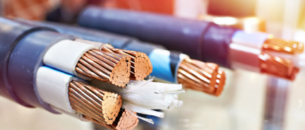
Choosing Cable for HVAC Branch Circuits
The MCA sets the conductor size. The installation location sets the cable type.
-
THHN/THWN-2 is the standard choice for conduit runs, indoors and outdoors.
-
XHHW-2 suits rooftop and wet locations and is exempt from the rooftop temperature adder in NEC 310.15(B)(2).
-
Type MC cable serves interior commercial branch circuits without a separate raceway.
-
NM-B and UF-B cover residential interior runs and direct burial. NM-B ampacity is limited to the 60°C column under NEC 334.80.
-
Mini split tray cable connects indoor and outdoor units on ductless systems.
-
Liquidtight flexible conduit makes the final connection at the unit and absorbs vibration.
For a deeper look at disconnects, overload protection, and room air conditioners, see Explaining NEC Article 440 on Air-Conditioning and Refrigeration Equipment.
Frequently Asked Questions
How do I calculate MCA if the nameplate is missing?
Start with the manufacturer's installation manual or spec sheet for that model number, since the listed value governs under NEC 110.3(B). If no published data exists, calculate it under NEC 440.32 and 440.33 from the compressor RLA and the fan FLA, which often appear on the compressor and motor labels: MCA = (1.25 × compressor RLA) + fan FLA + other loads. Confirm the result with the AHJ before you wire to it.
Can I use a larger wire than the MCA requires?
Yes. A larger conductor is always permitted and is often needed for voltage drop on long runs. Confirm that the unit's terminals accept the larger size.
Get the Right Wire for Your HVAC Circuit
The nameplate is where wiring for minimum circuit ampacity starts and ends: wire to the MCA, protect at or below the MOCP, and correct for the conditions of the run. Nassau National Cable stocks THHN/THWN-2, XHHW-2, MC cable, UF-B, and mini-split tray cable in every common HVAC size, cut to length, and shipped fast.
Сables Featured In This Blog


- Sale price
- $307.50
- Regular price
- $307.50