Garrie AI: Your Cable Guide


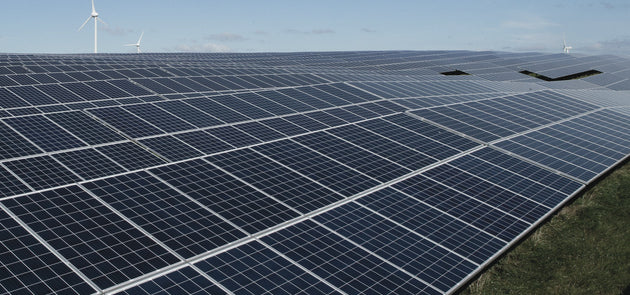
How to Wire Solar Panels?
Interested in installing your own solar panels? The best method to do that is series-parallel wiring. This guide explains everything you need to know about series–parallel solar panel wiring, including:
-
When and why to use this method
-
Step-by-step connection instructions
-
The right wire types and safety components
-
A visual diagram with updated terminology
-
Final installation tips for off-grid or hybrid systems
Why Choose Series–Parallel Solar Panel Wiring?
Wiring solar panels in series increases the voltage while maintaining the same current. Wiring in parallel increases the current while maintaining the same voltage.
Wiring solar panels in a series–parallel configuration allows you to get the best of both worlds:
-
Increased voltage (like in series wiring)
-
Increased current (like in parallel wiring)
This method is an optimal one, but it works best under the following conditions:
-
You need to charge a higher-voltage battery bank (e.g., 24V or 48V)
-
Your load demand exceeds what one wiring method can support
-
You want to maintain stable power delivery with more panels
Required System Components
Before you begin wiring, here’s what your system will typically include:
-
12-Volt / 120-Watt PV Modules (10A Rated)
-
MPPT Solar Charging Unit
-
Battery Bank (configured for 24V or 48V depending on load)
-
Power Inverter (DC to AC)
-
AC Appliances or Loads
-
DC Load Devices (optional)
-
Disconnects, breakers, fuses, and grounding hardware
Step 1: Wire the Solar Panels in Series–Parallel
Start by wiring your solar panels in a hybrid configuration. For example, if you have four 12V, 10A panels:
-
Connect the positive terminal of Panel 1 to the negative terminal of Panel 2 to form one series string.
-
Repeat this for Panels 3 and 4 to form a second string.
-
Now, you have two strings, each outputting 24V at 10A.
-
Combine the positive ends of both strings together, and do the same for the negatives. The final output is 24V at 20A.
For this step:
-
Use UL 4703 PV wire, rated for outdoor use, usually 10 to 12 AWG depending on current.
-
Add 15A or 20A inline fuses on each string before combining them.
-
Use MC4 branch connectors or a combiner box to join parallel strings safely.
Step 2: Connect the Panels to the MPPT Charge Controller
Take the combined output from your panels and run it into the PV array input terminals on your MPPT solar charge controller.
-
Place a DC disconnect switch between the array and controller to allow for safe maintenance or emergency shutdown.
-
Use 8 to 6 AWG stranded copper wire, depending on the system’s amperage and distance to the controller.
-
The MPPT controller steps down the voltage and regulates the current to efficiently charge the battery bank while preventing overcharging.
Step 3: Wire the Charge Controller to the Battery Bank
Now connect the charge controller’s DC output terminals to your 24V battery bank.
-
Use RHH/RHW-2 or DLO cable, rated for high-amperage DC use. For most systems, 2/0 to 4 AWG is common.
-
Install a DC-rated fuse or breaker near the battery's positive terminal for protection.
-
Configure your batteries in series (to increase voltage), parallel (to increase capacity), or series–parallel depending on your system requirements.
Ensure all terminals are torqued properly, and battery interconnects are clean and secure.
Step 4: Connect the Battery Bank to the Power Inverter
Your battery bank now feeds into the DC input side of your pure sine wave inverter, which will output standard 120V or 240V AC power.
-
Use DLO or welding cable between 2 AWG and 4/0 AWG, depending on inverter size and cable length.
-
Install a DC breaker or Class T fuse rated for high amperage.
-
Include a battery disconnect switch for safety during maintenance or emergencies.
Keep these cables as short and thick as possible to reduce voltage drop and heat buildup.
Step 5: Connect the Inverter’s AC Output to Your Home Loads
The inverter’s AC output terminals can now be wired to either a dedicated subpanel or directly to appliances.
-
Run THHN or THWN-2 copper wire, between 10 AWG and 6 AWG, based on the circuit amperage.
-
Use a transfer switch or automatic transfer switch (ATS) to safely isolate grid power from solar-generated power.
-
Each AC circuit should be protected with its own breaker or fuse in compliance with NEC Article 240.
This is the step where you determine which loads you want to power from the inverter. It will be either selected backup circuits or your whole home, depending on your inverter size and battery capacity.
Step 6: Ground the Entire System Properly
Grounding is vital for both system protection and code compliance. You need to bond all metallic components and provide a low-resistance path to ground.
-
Ground the solar panel frames, metal enclosures, controller, and inverter chassis.
-
Use bare or green insulated copper wire, sized 6 AWG to 8 AWG, depending on your system.
-
Connect to an appropriate grounding electrode such as a ground rod or Ufer ground, in line with NEC Article 250 and 690.43.
Infographic: Series–Parallel Wiring Setup For Solar Panels
Here’s a clear wiring diagram that shows exactly how your components connect. The labels have been updated for clarity. The highlights of the infographic:
-
Four 12V panels wired to create a 24V, 20A array
-
MPPT controller manages charging of the battery bank
-
24V, 400Ah battery bank provides storage
-
Inverter delivers AC to lights, fans, and other appliances
-
Switches and breakers isolate circuits for safety

Caption: Four 12V, 10A solar panels wired in series–parallel to deliver 24V, 20A to a 24V battery bank and AC/DC loads using an MPPT charge controller and inverter.
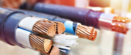
Cable Types You’ll Need
-
UL 4703 PV Wire
-
Used for: Connecting the solar panel array to the charge controller
-
Features: Rated for 600–2000V, UV-resistant, outdoor-rated, suitable for direct burial or exposed runs
-
DLO Cable
-
Used for: Connecting the battery bank to the inverter
-
Features: Rated for 2000V, extremely flexible, heat- and oil-resistant, ideal for high-current DC connections
-
RHH/RHW-2 Wire
-
Used for: Connecting the charge controller to the battery bank
-
Features: Flame- and moisture-resistant, approved for use in conduit, handles harsh indoor/outdoor environments
-
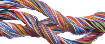
THHN/THWN-2 Copper Wire
-
Used for: Carrying AC power from the inverter to your subpanel or AC loads
-
Features: Colour-coded for phase identification, suitable for conduit, wet or dry locations, rated 600V
-
Ground Wire
-
Used for: Bonding all metal components and enclosures to ground
-
Features: Typically 6–8 AWG, bare or green copper, must comply with NEC Article 250 for grounding and bonding
Final Installation Checklist
-
Your panel wiring (series, parallel, or series–parallel) matches your voltage and current requirements
-
Proper wire gauge and insulation types used for each section
-
Inline fuses, breakers, and disconnects are installed
-
Battery bank is matched to system voltage and inverter specs
-
All components are grounded per the NEC code
-
Switches and breakers isolate each AC load
-
The system is labelled, secured, and verified before powering on
Nassau National Cable sells UL 4703 PV wire, DLO cable, RHH/RHW-2 wire, THHN/THWN-2 copper wire, and grounding wire for complete solar power system wiring.