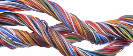
Garrie AI: Your Cable Guide


NEC Wire Gauge Chart
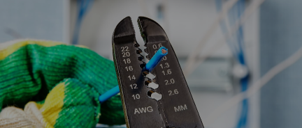
AWG stands for American Wire Gauge. It's a logarithmic numbering system for conductor size, standardised in 1857 and still the North American default for building wire. Any wire size chart or AWG wire chart you've ever seen traces back to this scale. The smaller the AWG number, the larger the wire. A 4/0 ("four-aught") conductor is massive—about 11.7 mm (0.46 in) in diameter; a 14 AWG conductor, at about 1.63 mm (0.064 in) in diameter, is what you'd find in a typical lamp cord.
The scale runs from 1 AWG to 1/0, then jumps to 2/0, 3/0, and 4/0. Above 4/0, AWG numbering stops and sizes are measured in thousand circular mils (kcmil) — 250, 300, 350, 500, 750, 1000 kcmil are all standard feeder and service sizes.
A complete AWG wire size chart shows six data points per gauge: diameter in inches and millimetres, cross-sectional area in kcmil and mm², DC resistance per 1000 feet, and ampacity across three temperature columns. Everything on the chart derives from the conductor's physical dimensions, and ampacity is the only column that depends on external factors.
Where the NEC wire ampacity chart numbers come from
The ampacity values on every electrical wire size chart in North America come from NEC Table 310.16 — the National Electrical Code's reference table for allowable ampacities of insulated conductors in raceway, cable, or direct burial. NEC is the baseline standard for permanent electrical installations in the United States. Every building wire ampacity you'll see on a spec sheet or online traces back to that document.
The table assumes specific conditions:
-
No more than three current-carrying conductors in a raceway or cable.
-
Ambient temperature of 30°C (86°F).
-
Standard insulation types matched to each temperature column.
Change any of those conditions, and the ampacity changes too. That's where derating comes in, and it's a section unto itself later in this post.

The 60°C, 75°C, and 90°C columns explained
The three temperature columns on the NEC wire ampacity chart are not three different ampacity ratings you can choose between. They correspond to three different insulation temperature ratings, each tied to specific insulation types.
The 60, 75, and 90°C values (140, 167, and 194°F) are the maximum continuous operating temperatures at which the respective insulation materials can be used without degrading. If pushed above those limits, the insulation starts to break down cumulatively. A conductor running at 5°F over its rating for a decade will fail long before one kept at its rated temperature.
Each column is set by the weakest insulation in its category:
-
60°C (140°F) — the thermal ceiling for older thermoplastic compounds, primarily the PVC formulations used in NM-B and UF-B. These insulations were standardised for residential use decades ago, when cheap PVC was the default material. They're flexible, easy to strip, and inexpensive, but the PVC starts to soften and migrate above about 140°F.
-
75°C (167°F) — the rating for modern thermoplastic insulations like THW, THWN, SE, USE, and XHHW. The "W" in most of these names stands for wet-rated — these compounds resist water absorption, which is why they're approved for conduit fill, underground raceways, and service entrance use. The 75°C rating reflects improved plasticiser stability and better heat resistance than the 60°C compounds, but they're still thermoplastics that soften gradually with heat.
-
90°C (194°F) — the rating for cross-linked insulations like THWN-2, THHN, XHHW-2, and USE-2. Cross-linking chemically bonds the polymer chains into a three-dimensional network, so the material doesn't flow or soften with heat — it becomes a thermoset rather than a thermoplastic. That's what lets it sit at 194°F indefinitely. But the 90°C column is rarely used for final ampacity on its own, because terminations (breakers, lugs, equipment) are rarely rated that high. The column's real purpose is as a starting point for derating calculations, covered below.
Why the 90°C column doesn't work on its own
The conductor is only one part of a circuit. Every wire ends at a terminal — a breaker lug, a switch screw, an equipment connector. Those joints heat up due to contact resistance, and each terminal has its own UL-listed temperature rating that sets the maximum temperature the joint can reach.
That rating indicates the maximum temperature the terminal assembly can withstand. Most common terminations fall into two categories:
-
Standard residential and light commercial breakers, switches, outlets, and small equipment: rated 60°C (140°F) at the terminals.
-
Larger commercial and industrial breakers, lugs, and equipment (generally 100 A and above): rated 75°C (167°F) at the terminals.
Very few field-installed terminations are rated 90°C (194°F). Those exist mostly on specialized industrial equipment, motor terminations on large motors, and some purpose-built medium-voltage gear. The ordinary breakers, lugs, and disconnects you'll find in a typical panel will never have the 90°C rating.
Say 6 AWG THHN carries 75 A fine by its 90°C rating — but landed on a 75°C breaker terminal, the joint cooks past 167°F. NEC 110.14(C) requires sizing from the column that matches the terminal, not the wire. That drops the same 6 AWG THHN to the 75°C column (65 A), meaning it can't carry 75 A on a 75°C-rated terminal even though the wire alone could handle it.
So when is the 90°C column useful at all?
Derating. When you have to reduce ampacity due to high ambient temperature or bundled conductors, the correction factors eat into the starting value you use. Starting from a higher column gives you more ampacity to lose before you fall short.
Example: you need to run 50 A through a conduit with 9 current-carrying conductors in an ambient environment of 40°C (104°F), terminating on a 75°C-rated breaker. The bundling factor is 0.70, and the ambient correction at 90°C insulation is about 0.91. Total derate: 0.64.
-
If you start from 8 AWG THWN in the 75°C column (50 A): 50 × 0.64 = 32 A. Not enough.
-
If you start from 8 AWG THHN in the 90°C column (55 A): 55 × 0.64 = 35 A. Still not enough.
-
If you start from 6 AWG THHN in the 90°C column (75 A): 75 × 0.64 = 48 A. Still not quite enough.
-
4 AWG THHN in the 90°C column (95 A): 95 × 0.64 = 61 A. Works — and the final ampacity (61 A) is below the 75°C column value for 4 AWG (85 A), so the termination is safe.
The 90°C column gave you the headroom to do the derating math without jumping up to a 2-conductor size.
Quick column-selection rule
-
Circuits 100 A or less (or wired with 14–1 AWG): terminations are typically 60°C-rated unless specifically marked otherwise. Use the 60°C column.
-
Circuits over 100 A (or wired with conductors larger than 1 AWG): terminations are typically 75°C-rated. Use the 75°C column.
-
The 90°C column: used for derating math only. Start from 90°C, apply ambient and bunding factors, and verify the result falls within the termination's rated column.
Copper vs aluminum
The wire gauge chart splits into two tables because copper and aluminum behave differently. Aluminium conductors have roughly 60% the conductivity of copper per unit cross-sectional area, which means an aluminium conductor needs to be larger to carry the same current.
Practical consequences of that split:
-
Upsizing. An aluminium feeder typically needs to be 1 to 2 AWG sizes larger than the equivalent copper feeder. A 200-A copper service runs on 2/0 copper; the aluminium equivalent is usually 4/0.
-
No 60°C column. Aluminium isn't manufactured in NM-B or UF-B sizes for building wire, so the 60°C column doesn't apply. The aluminum wire sizing chart starts at 75°C.
-
Smallest size. Aluminum building wire starts at 12 AWG. You won't find 14 AWG aluminum in the field, as the mechanical properties don't work at that size for typical terminations.
-
Termination compatibility. Aluminum requires lugs and breakers marked CU/AL or AL/CU. Mixing aluminum conductors with copper-only terminations causes galvanic corrosion and loosening over time.
Aluminum is standard for utility service conductors, large feeders, and most installations where the cost of copper is too high. For branch circuits, copper is the choice. It is cheaper per foot at small sizes, mechanically more forgiving, and avoids the history of problems with 1960s-era aluminium branch wiring.
What the diameter, area, and resistance columns are for
Ampacity gets most of the attention on any gauge wire chart, but the physical columns matter for different design questions:
-
Diameter (in/mm) — used for conduit fill calculations (NEC Chapter 9, Table 5), bending radius limits, and sizing cable glands or terminations.
-
Area (kcmil/mm²) — used for short-circuit current calculations, parallel conductor sizing, and cross-referencing international cable specifications. Most European and international cables are specified in mm².
-
DC resistance (Ω/1000 ft) — used for voltage drop calculations on long runs. NEC recommends keeping the combined total voltage drop under 5% (branch + feeder) and under 3% for branch circuits alone. Resistance × length × current × 2 (for round-trip) gives you the drop.
Resistance values are DC at 20°C. For AC circuits with larger conductors, skin effect introduces a small correction — usually under 5% for 60 Hz power work, but relevant for precision applications.
Two rules that override the chart
NEC adds two constraints that don't appear in the ampacity columns themselves, but that apply to every residential and small-commercial circuit:
Small conductor rule (NEC 240.4(D))
Regardless of what the ampacity column shows, 14 AWG copper is limited to 15 A overcurrent protection, 12 AWG to 20 A, and 10 AWG to 30 A. A 10 AWG THHN shows 40 A in the 90°C column — but you can't put a 40 A breaker on it. This rule exists because small conductors at their thermal limit don't coordinate well with standard residential breakers.
Terminal temperature rating (NEC 110.14(C))
The conductor you install must be sized to the lowest-rated component in the circuit. If any part of the circuit — breaker, lug, disconnect, or equipment terminal is rated 75°C, you can't use 90°C column ampacity for sizing. The 90°C rating only helps for derating calculations.
Together, these two rules explain why residential 20 A circuits almost always use 12 AWG copper: the small conductor rule caps it there, and the terminal rating caps the ampacity you can draw from the chart.
Derating for ambient temperature and bundling
The ampacity values on the chart assume a 30°C (86°F) ambient temperature and no more than 3 current-carrying conductors in the same raceway. Most real installations break one or both of those assumptions, and NEC requires you to derate accordingly. Skipping the derating math is how conductors run hot, insulation degrades, and circuits fail inspection.
Heat is the only thing you're managing. Every ampacity limit exists because current generates I²R losses, which convert to heat. The insulation can only absorb so much before it degrades. Anything that raises ambient temperature or reduces the conductor's ability to shed heat cuts into the margin.
Ambient temperature correction (NEC Table 310.15(B)(1))
When ambient temperature exceeds 86°F (30°C), you multiply the base ampacity by a correction factor. The factor depends on both the actual ambient temperature and the conductor's insulation rating. Higher-rated insulation has more thermal margin, so the correction factor is less aggressive.
Representative values from NEC 310.15(B)(1) for copper conductors:
-
21–25°C (70–77°F) ambient: 60°C insulation × 1.08, 75°C × 1.05, 90°C × 1.04 (you can actually increase ampacity slightly in cool environments).
-
31–35°C (88–95°F) ambient: 60°C × 0.91, 75°C × 0.94, 90°C × 0.96.
-
36–40°C (97–104°F) ambient: 60°C × 0.82, 75°C × 0.88, 90°C × 0.91.
-
41–45°C (106–113°F) ambient: 60°C × 0.71, 75°C × 0.82, 90°C × 0.87.
-
46–50°C (115–122°F) ambient: 60°C × 0.58, 75°C × 0.75, 90°C × 0.82.
The pattern matters more than the exact numbers. At 122°F (50°C) ambient — common in rooftop conduit runs, attics in hot climates, and industrial spaces near heat-generating equipment — a 60°C (140°F) NM-B cable loses 42% of its ampacity. A 90°C (194°F) THWN-2 only loses 18%. This is why higher-temperature insulation gets specified for harsh environments: it's not about running the wire hotter, it's about retaining more of its rated ampacity when the environment is working against you.
The 86°F (30°C) baseline assumes mild, interior conditions. Real installation sites often sit well above that:
-
Rooftop conduit in direct sun: NEC 310.15(B)(2) adds a temperature adder based on height above the roof. A conduit within 7/8 inch of a hot rooftop can raise the ambient by 60°F (33°C), pushing the effective ambient to 140°F (60°C) or higher.
-
Attics in the southern US regularly see summer peaks of 122–140°F (50–60°C).
-
In industrial boiler rooms, mechanical equipment rooms, and generator rooms, sustained ambient temperatures of 104–113°F (40–45°C) are common.
-
Underground in hot climates: soil temperature at conduit depth is usually more moderate—68–77°F (20–25°C)—but nearby heat sources like steam lines change the equation.
-
Data centers and server rooms: typically cool, 68–75°F (20–24°C), but cable trays stacked above hot aisles can run warmer than the room setpoint.
For rooftop installations specifically, the 2017 NEC and later editions adjusted the rules — current code references NEC 310.15(B)(3)(c) for rooftop temperature adjustment, and the adder is less aggressive for conduit raised above the roof surface. Check the exact values in the code edition your jurisdiction has adopted.
Bundling correction (NEC Table 310.15(C)(1))
The chart assumes three current-carrying conductors. Here is how to count more:
-
4–6 current-carrying conductors: multiply ampacity by 0.80.
-
7–9: multiply by 0.70.
-
10–20: multiply by 0.50.
-
21–30: multiply by 0.45.
-
31–40: multiply by 0.40.
-
41 or more: multiply by 0.35.
The neutral in a balanced three-phase circuit doesn't count as current-carrying (NEC 310.15(E)), and neither does a grounding conductor. The neutral does count for LED lighting, VFDs, and switch-mode power supplies.
Stacking ambient and bundling corrections
Both correction factors apply simultaneously, and they multiply rather than add. A bundle of 8 conductors in 104°F (40°C) ambient, all THWN-2 (90°C/194°F rated), looks like this:
Base ampacity (90°C column, from chart) × 0.91 (ambient) × 0.70 (bundling) = 0.637 × base ampacity.
That derated value then has to land within the 75°C column's limit at your termination, because 110.14(C) still governs the final installation ampacity. If a 3/0 THWN-2 rated 225 A in the 90°C column derates to 225 × 0.637 = 143 A, and your termination is 75°C rated (3/0 = 200 A in that column), you're fine — 143 is well under 200. If the numbers had landed the other way, you'd have to upsize the conductor.
This is the practical reason to start with 90°C-rated insulation in any installation where derating is likely. The higher starting ampacity gives you more margin to absorb the correction factors. Starting from a 60°C base and aggressively derating often results in unnecessary upsizing.
How to size a conductor using the wire size chart
The chart makes sizing a three-step decision when you work through it in order:
1. Identify your load current and termination rating. Determine the continuous current the circuit will carry, multiply by 1.25 if it's a continuous load (NEC 210.19(A)), and check whether your breaker and equipment terminations are rated 60°C or 75°C.
2. Pick the copper or aluminum table. Most branch circuits are copper. Large feeders and service conductors are often aluminum.
3. Read the correct ampacity column. 60°C for small circuits with standard terminations, 75°C for larger circuits with 75°C terminations. Find the smallest conductor whose ampacity meets or exceeds your required current. Then check the small conductor rule for 14, 12, and 10 AWG copper.
If your installation has a high ambient temperature or more than three current-carrying conductors in the raceway, start with the 90°C column, apply derating factors, and verify that the derated value still meets your load in the termination column.
The American wire gauge chart is a reference. Code compliance still requires following NEC 110.14(C), 240.4(D), and the derating provisions in 310.15 — the chart tells you what the wire can carry, but it doesn't make the installation decisions for you.
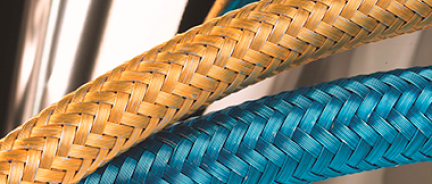
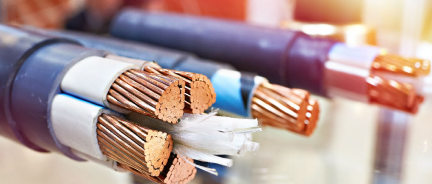
Common building wire and cable types
The ampacity columns on the chart are tied to specific insulation types, but the types themselves deserve their own rundown. Nassau National Cable stocks all of the following in copper and, where applicable, aluminum.
Branch circuit and general-purpose wire
-
THHN / THWN-2 — the workhorse building wire. PVC insulation with nylon jacket, 90°C dry and 75°C wet rating, rated for use in conduit or cable trays. Stocked in sizes from 14 AWG through 1000 kcmil.
-
NM-B (Romex-style) — nonmetallic-sheathed cable for residential branch circuits. 60°C rated, limited to dry indoor locations, 14–2 AWG.
-
UF-B — underground feeder cable, direct burial rated. 60°C, suitable for outdoor circuits to sheds, garages, and landscape lighting.
-
XHHW-2 — cross-linked polyethene insulation, 90°C wet and dry. Better chemical resistance than THHN, common in industrial and wet locations.
Service entrance and feeder cable
-
SE / SEU / SER — service entrance cable, used from the utility connection to the meter and main panel. Available in aluminum for most service sizes.
-
USE / USE-2 — underground service entrance cable, direct burial rated for utility service drops.
-
URD — underground residential distribution, typically aluminum, used for secondary service to residential buildings.
Medium voltage and utility cable
-
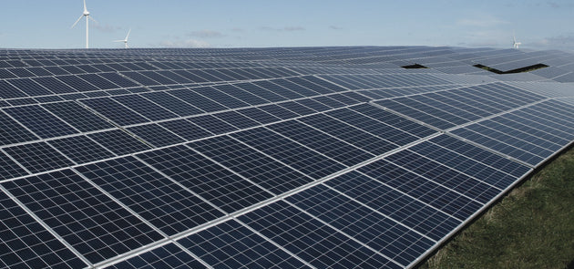
MV-105 / MV-90 — medium voltage cable rated 5 kV through 35 kV, for industrial distribution, utility-scale solar, and data center incoming service.
-
Tray cable (TC / TC-ER) — multi-conductor cable rated for cable tray installation, common in industrial control and power distribution.
Specialty cable
-
Instrumentation and control cable — shielded multi-pair and triad cables for process control, 4–20 mA signalling, and data acquisition.
- Photovoltaic (PV) wire — single-conductor wire rated for solar array DC circuits, sunlight and moisture resistant, 90°C wet rated.