¿Cómo cablear un abridor de puerta de garaje?
Un abridor de puerta de garaje es un dispositivo que abre automáticamente la puerta mediante un interruptor o control remoto. El cableado de un abridor de puerta de garaje implica conectar la alimentación, los sensores y los controles al motor. Aquí tienes una guía paso a paso para ayudarte a cablearlo correctamente:

Herramientas y materiales:
- Destornillador
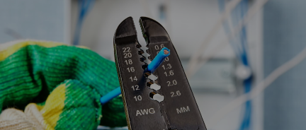
- Pelacables
- Taladro (si se montan sensores)
- Cinta aisladora
- Escalera
- Manual de instalación del abridor de puertas de garaje
- Guantes y gafas de seguridad
Paso 1: Preparaciones
- Desconecte la energía del garaje desde el disyuntor para evitar descargas eléctricas.
- Lea atentamente las instrucciones del fabricante para conocer los requisitos de cableado específicos.
Paso 2: Monte el abridor de la puerta del garaje
- Instale el motor del abridor en el techo utilizando los soportes provistos.
- Asegure el brazo abridor a la puerta según las instrucciones.
Paso 3: Conecte la fuente de alimentación
Modelos enchufables:
- Conecte el abridor a un tomacorriente elevado cerca del motor.
Modelos cableados:
- Conecte los cables de alimentación del abridor al cableado de la casa.
- El cable negro se conecta al cable activo.
- El cable blanco se conecta al cable neutro.
- El cable verde o desnudo se conecta a tierra.
- Asegure las conexiones con tuercas para cables y cinta aisladora.
Paso 4: Conecte los sensores de seguridad
- Coloque los sensores :
- Coloque un sensor a cada lado de la puerta del garaje, aproximadamente a 6 pulgadas del suelo.
- Alinee los sensores para que queden uno frente al otro.
- Pase los cables :
- Utilice el cableado proporcionado para conectar cada sensor a la unidad del motor.
- Normalmente, los cables son de bajo voltaje y están codificados por colores:
- El cable blanco va al terminal denominado "blanco" o "común".
- El cable con rayas blancas y negras se conecta al terminal de "seguridad".
- Cables seguros :
- Utilice clips o grapas para pasar los cables por las paredes y el techo sin pincharlos.
Paso 5: Conecte el panel de control de pared
- Monte el panel :
- Coloque el panel de control en la pared, a la altura de los ojos, cerca de la puerta del garaje.
- Perfore agujeros y utilice los tornillos proporcionados para un montaje seguro.
- Conecte los cables :
- Pase los cables desde el panel hasta la unidad del motor.
- Conecte los cables a los terminales designados tanto en el panel como en la unidad del motor, siguiendo el código de colores.
Paso 6: Pruebe las conexiones
- Restaurar energía :
- Vuelva a encender el disyuntor.
- Alinear sensores :
- Asegúrese de que los sensores de seguridad estén correctamente alineados (las luces indicadoras deben estar fijas).
- Pruebe el abridor :
- Presione el control de pared o el control remoto para garantizar que la puerta se abra y se cierre suavemente.
- Pruebe el mecanismo de reversa de seguridad bloqueando la trayectoria del sensor u obstruyendo la puerta.
¿Cuántos amperios necesita un abridor de puerta de garaje?
La capacidad de un abridor de puerta de garaje depende del consumo de energía y del tipo de abridor de puerta, pero en general:
Abre-puertas de garaje residenciales :
- Potencia : La mayoría de los modelos tienen una potencia nominal entre 1/3 HP y 1 HP .
- Consumo de corriente : entre 5 y 10 amperios a 120 V.
Abridores de puertas de garaje comerciales :
- Los modelos más grandes pueden consumir entre 10 y 15 amperios o más.
Dimensionamiento de cables para abridores de puertas de garaje
El cable debe soportar el amperaje de forma segura sin sobrecalentarse:
- Para un consumo de 5 a 10 amperios :
- Utilice cable de 14 AWG .
- Ideal para abridores de puertas de garaje estándar en un circuito de 15 amperios.
- Para un consumo de 10 a 15 amperios :
- Utilice cable de 12 AWG .
- Adecuado para abridores de servicio pesado o circuitos con cargas adicionales.
Qué tener en cuenta:
- Utilice un disyuntor de 15 amperios para un solo abridor en un circuito dedicado.
- Para circuitos compartidos, puede ser necesario un disyuntor de 20 amperios , dependiendo de la carga total.
- Muchos fabricantes recomiendan un circuito dedicado de 120 V para el abridor para evitar interrupciones de energía.
- Para tramos de más de 50 pies de longitud, considere aumentar el tamaño del cable (por ejemplo, 12 AWG en lugar de 14 AWG) para reducir la caída de voltaje.
- El consumo de energía en modo de espera del abridor de la puerta del garaje es insignificante (por ejemplo, 1-1,5 amperios).
Tipos de cables para abridores de garaje
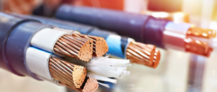
El tamaño y tipo de cable para un abridor de puerta de garaje dependen de la fuente de alimentación, el cableado de control y las conexiones del sensor de seguridad. A continuación, se detalla:
Cable de alimentación
Este cable conecta el abridor de la puerta del garaje a una toma de corriente o directamente al sistema eléctrico de la casa.
- Tipo : Utilice cable NM-B (Romex) para cableado residencial estándar.
- Calibre : 14 AWG suele ser suficiente para un abridor de puerta de garaje, ya que la mayoría funciona a 5-10 amperios. Use 12 AWG si el abridor comparte circuito con otros dispositivos o electrodomésticos.
- Voltaje : 120 V (estándar en la mayoría de los garajes residenciales).
- Notas : Consulte los códigos de construcción locales; algunos requieren cableado o un circuito dedicado.
Cableado del sensor de seguridad
Este cable de bajo voltaje conecta los sensores de seguridad del fotocélula a la unidad del motor del abridor.
- Tipo : Utilice cable trenzado de bajo voltaje .
- Calibre : 22 AWG es estándar para la mayoría del cableado de sensores de apertura de puertas de garaje.
- Conductores : Generalmente se requiere un cable de 2 conductores (por ejemplo, blanco y con raya blanca/negra).
- Notas : Utilice el cableado preinstalado o utilice cable de timbre para facilitar la instalación. Asegúrese de que sea apto para aplicaciones de bajo voltaje.
Cableado de control de pared
Esto conecta el panel de control montado en la pared a la unidad del motor.
- Tipo : Utilice cable trenzado de bajo voltaje o cable de termostato .
- Calibre : 22 AWG o 18 AWG es suficiente.
- Conductores : Generalmente se requiere un cable de 2 conductores (blanco y rojo o código de colores similar).


