How to Wire a Receptacle Outlet?
Wiring a receptacle outlet, the standard 120V duplex outlet found in most U.S. homes, is a straightforward electrical task when safety and proper wiring practices are followed. This guide walks you through replacing or installing a grounded, always-on, non-switched receptacle outlet.
What Is a Receptacle Outlet?
A receptacle outlet, a standard 120V duplex outlet, provides two plug-in slots (top and bottom) powered by the same circuit. These outlets deliver 120 volts of alternating current (AC) and power everyday items like lamps, TVs, toasters, phone chargers, and more.
Why Wiring a Receptacle Outlet Is Different
Wiring a standard receptacle outlet is simpler and more beginner-friendly than wiring other outlets, such as GFCI, split, or switched outlets. Here's why:
-
Always-on: There’s no switch control or tab separation required because both sockets remain powered continuously.
-
No internal devices: Unlike GFCIs or AFCIs, there are no test/reset buttons or required line/load connections.
-
Unified circuit: The metal tabs between the two brass screws and between the two silver screws remain intact, allowing power to flow to both sockets from a single hot and neutral connection.
-
Straightforward wiring layout:
-
Black (hot) to brass screw
-
White (neutral) to silver screw
-
Bare or green (ground) to green screw
This makes receptacle outlets the most common and most straightforward to install.
Cables Used to Wire a Receptacle Outlet
Cable choice depends on the circuit amperage and the environment.
For Indoor Use (Dry Locations)
For Wet or Outdoor Use
-
UF-B Cable (Underground Feeder):
For Use in Conduit
-
THHN/THWN-2 Wires in EMT or PVC Conduit:
-
Common sizes:
-
14 AWG THHN for 15A receptacle outlets
-
12 AWG THHN for 20A receptacle outlets
-
When using THHN, you must run separate hot, neutral, and ground wires inside the conduit.
Wiring Methods for Receptacle Outlets
When the receptacle outlet is part of a circuit that continues to other devices (such as another outlet or a light), there are two accepted methods for wiring:
-
Direct Wiring (pass-through):
-
Connect one wire to each of the two brass screws (hot) and one to each silver screw (neutral). This method passes power through the outlet to the next device.
-
Pigtailing (preferred):
-
Use wire nuts to join all hot wires together and add a short pigtail to the brass screw. Repeat for neutral and ground wires.
-
This improves safety and makes it easier to replace the outlet in the future without disturbing the rest of the circuit.
Important: If your box contains more than two cables, pigtailing is required. Never place more than one wire under a single screw, as this is unsafe and not code-compliant.
Tools & Materials
-
Wire stripper
-
Screwdriver
-
Needle-nose pliers
-
Voltage tester
-
NM cable (14/2 or 12/2)
-
Electrical box
-
Receptacle outlet (15A or 20A)
-
Wire nuts

![]() Wiring A Receptacle Outlet Step By Step
Wiring A Receptacle Outlet Step By Step

1. Safety First
-
Turn off the power: Switch off the appropriate circuit breaker.
-
Test for power: Use a voltage tester to confirm the outlet is fully de-energized.
2. Remove the Old Receptacle Outlet (if replacing)
-
Remove the faceplate: Unscrew and detach it.
-
Disconnect the wires: Loosen the terminal screws and detach the wires.
3. Prepare the Wires
-
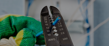
Strip insulation: Expose about ¾ inch of bare copper.
-
Create hooks: Bend each wire end into a clockwise hook using needle-nose pliers.
4. Connect the Wires
Each wire connects to a specific screw terminal on the receptacle outlet:
-
Ground wire (bare or green): Attach to the green screw (bottom side)
-
Neutral wire (white): Attach to the silver screw (left side)
-
Hot wire (black): Attach to the brass screw (right side)
These terminal screws are designed to hold each wire and ensure proper electrical contact securely. The green screw connects to the outlet frame (ground), the silver screw to the neutral circuit, and the brass screw to the live power source.
Wrap each wire clockwise around its terminal and tighten firmly.
If you're using pigtails, connect all the wires together using wire nuts, and run a short pigtail to each terminal.
5. Secure the Receptacle Outlet
-
Tuck the wires: Gently fold them back into the box.
-
Mount the outlet: Align and secure it using mounting screws.
6. Finish Up
-
Attach the faceplate: Screw it in place.
-
Restore power: Flip the breaker back on and test the outlet with a tester or plug-in device.
How Many Receptacle Outlets Per Circuit?
To avoid overload:
-
15A breaker: Up to 8 outlets
-
20A breaker: Up to 10 outlets
This assumes moderate use at about 1.5 amps per outlet.
Additional Safety Tips
-
Use 14 AWG wire for 15A circuits and 12 AWG for 20A.
-
Never use push-in terminals. Use side screws that are safer.
-
Tighten all connections firmly and double-check with a tug test.
-
Don’t overcrowd electrical boxes - check box fill limits to avoid this mistake.
-
Only use UL-listed receptacle outlets and materials.
-
Replace any outlet or cable showing wear, heat, or damage.


